Although I've always wanted to build a flash lamp pumped dye laser, I've refrained from any serious attempts until now. In my mind, there were too many variables to nail down - too many uncertainties. I was discouraged by the relationships of OC reflectivity (and respective transmissivity), dye concentration, pump energy and circuit inductance. The possible variations seemed overwhelming. The availability, cost and relatively esoteric nature of high voltage capacitors were yet another deterrent. All of this changed however when I encountered the brillient work of [1]Sothory Yun. Sothory Yun managed to build lasers with the most basic and common supplies imaginable. Best of all, he presented working examples of dye lasers that did not require commercial HV capacitors! The lamp pumped dye laser had been moved within reach owing to Sothory Yun's work, but I was still hesitant due to my distractions with other projects. A final push was made by a friend in South Africa, Chris Hill. Chris had been wanting to build a dye laser for quite some time. During the course of our ongoing correspondence, Chris said bluntly "You should build a dye laser" - this statement was a final straw, and it resulted in my decision to make a serious attempt to build a flash lamp pumped dye laser.
The following three parameters, unique to dye lasers, are the most challenging considerations:
- Energy per unit volume
- Dye concentration
- Circuitry inductance
The following parameters are more general in nature, but they still represent a formidable challenge to the successful construction of a operating dye laser device:
- Resonator mirror alignment
- Resonator mirror types
- Gain medium alignment
Ongoing work:
Capacitor Design:
Energy per unit volume
Based upon the wonderful work of Sothory Yun, I've calculated an energy to volume ratio of 2.6E-2J/mm^3, or (conversely) a volume to energy ratio of 38mm^3/J. The genius behind Mr. Yun's "pocket" dye laser is that it is scaled down to the point where it can be pumped by very simple homemade capacitors.
My calculation serves as a point of reference whereby the required energy can be found for a device based upon the volume of its amplifying medium. The calculation provides a very general figure, as it does not take into account other important factors (namely dye concentration). The accuracy or effectivity of the calculation remains to be determined experimentally - this is a work in progress on my part. As of the writing of this text, I have not constructed my first successful flash lamp pumped dye laser!
• Application:
I plan to use an amplifier tube that is roughly twice the diameter of that recommended by Mr. Yun. In addition, my lamps arc length is 30mm (which can basically be thought of as the active length how the amplifier tube) as opposed to Yun's suggested 25mm. So what this all translates to is:
Step 1:
Volume = pi*r^2*h
3.14*(1.25mm^2)*30mm
3.14*1.6mm^2*30mm
Volume ≈ 150mm^3
Step 2:
Volume to energy ratio ≈ 38mm^3/J
1 Joule/38mm^3 * 150mm^3
3.95J
Required energy based upon ratio = 4 Joules
Dye concentration
Dye concentration is another factor that, in my estimation, must vary based upon other factors such as output coupler reflectivity, pump energy and amplifier tube diameter. Fortunately the guess work is eliminated by Sothory Yun's example. He provides an extremely easy way to determine the required dye concentration, using an ordinary green laser pointer. The concentration would likely need to be reduced if using an amplifier tube that is substantially larger in diameter than that recommended by Sothory Yun, and the output coupler reflectivity would presumably need to be increased accordingly. But this is a very general assumption on my part and even if I am correct, I do not know how to quantify everything in a common formula so that all of these factors can be adjusted proportionally. The best approach is to base ones design on something that has been proven to work, and then make experimental changes as desired. In the absence of adequate theory, initial design in the form of guesswork (as opposed to a design based heavily upon a successful example) will likely result in an exhaustive exercise in futility.
To be continued ...
Ongoing Work
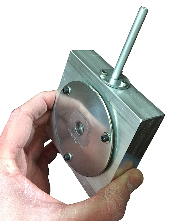
My original plan was to make the 'end pieces' out of recycled HDPE. There are numerous YouTube examples of DIY recycling of HDPE. I quickly abandoned the idea however when I discovered bubbles or air-pockets in my solid HDPE pieces.
Capacitor design:
This is a drawing representing the capacitor. The view is from the edge. Blue lines represent the transparent sheets that serve as dielectrics. Red lines and black lines represent conductive aluminum foil sheets. All red foils are at one polarity and all black foils are at the opposite polarity. The foils are staggered so that they extend past the dielectric sheets. These extended foil sections serve as electrical connections to the capacitor. These electrical connections are used to apply and extract charge from the capacitor. The dielectric sheets (blue) store energy in the form of electric charge, and each dielectric sheet, with its adjacent aluminum foil sheets, form a single capacitor. The diagram shows many such 'single capacitors' combined in order to provide a sum of the individual capacitances.

Remember that red and black represent conductive aluminum foils, separated by dielectric sheets, with opposite polarities corresponding to the color difference. All dielectric sheets are indicated by the color blue. So the first diagram has 3 colors representing two different types of materials. From the perspective of this diagram, the edges of side "C" and side "D" are visible to the left and right. Side "A" indicates the top and side "B" represents the bottom of the stack. If the perspective is changed so that an observer is positioned directly over side "A", then the edges of four sides become visible. These sides are "C" , "D" , "E" and "F". This new perspective is illustrated in the following drawing.
In order for the arrangement to work, the aluminum foils must be offset to their respective sides, with care taken to ensure that opposing foils are always separated by dielectric foils. No two foils of opposing polarity can come in direct contact - such a condition will result in a dead electric short.
The arrangement cannot be rolled up without at least one extra dielectric foil on the top or bottom (i.e. side "A" or side "B"). There should be an even number of aluminum foil layers, and the top and bottom aluminum foil layers will be at opposite polarity. Therefore at least one dielectric foil must be on the very top or very bottom, which will then allow the entire arrangement to be rolled up without having the top aluminum foil contacting the bottom aluminum foil. This is a very simple yet imperative detail.

Starting from side "E" or "F" roll the arrangement tightly around a dowel rod or some other cylinder-shaped structure. I rolled mine around a section of thick glass tubing. The glass had an OD of about 10mm, but this diameter was somewhat based upon convenience. The thicker the arrangement, the more difficult it will be to roll it tightly. Furthermore, a smaller radius of curvature will result in more misalignment of the foil layers. So use common sense by rolling it around something that seems reasonable for its thickness. In short, don't get too carried away by trying to roll it too rightly.


The capacitor stack should be rolled up like a sleeping bag. Once complete, apply tape around the outside. Be generous with the tape and wrap it all-the-way around the roll. Apply the tape in discrete wraps, spaced at several locations along the length of the roll.
I don't recommend wrapping the tape like bandages around a mummy, because you might need to cut the tape off and unwrap it at some point. If one of the dielectrics were to fail, you might want to repair the capacitor by replacing this dielectric. At the very least, you would probably want to salvage the good dielectrics for use in another capacitor. So apply just enough to tape to keep the roll together, and keep the strips of tape confined to a few narrow sections that are spaced along the length of the capacitor.


The aluminum foils extend outside the ends of the roll. These foils must be squeezed tightly together so that they are in electrical contact. The unified foils on opposing ends are thus the electrical connections to the capacitor. These connections are used to apply and retrieve electric charge.

Don't be deceived by the relatively benign appearance of this crude structure. It can easily store a lethal charge. The low inductance and internal resistance means that this capacitor can release its energy extremely fast, thereby providing extraordinary power. The high voltage means that deadly current can be passed through the human body.
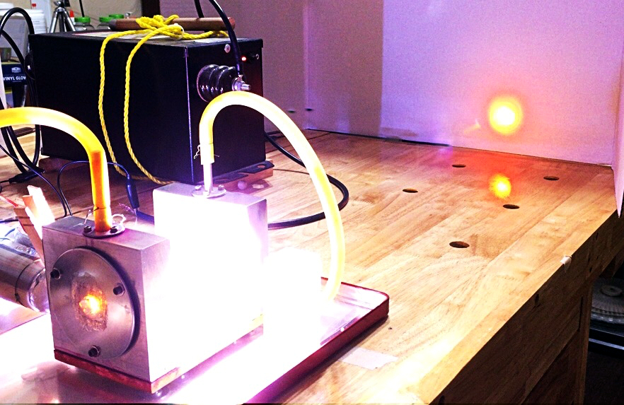
Here are my two capacitors being tested with a 3mm arc-length camera flash.


Be sure to wear safety glasses and hearing protection - lamps can undergo catastrophic failure when driven harder than what they were designed for. Camera flashes are only designed for a few joules, and certainly not at the insane power levels that these homemade capacitors provide. The hearing protection is for the spark gap, but eye protection is required for high velocity glass shards from an exploding lamp!