Copper Chloride Laser

WARNING: Construction and operation of any laser device is hazardous. Do not attempt to construct or operate a laser without adequate safeguards and safety practices. Most lasers involve high voltages, toxic chemicals, high vacuum, laser radiation and other hazards. The author specifically disclaims any and all liabilities associated with the construction and use of such devices. Designs presented here are in the interests of providing information on operational principles only and do not represent safe nor ANSI safety compliant designs.


I take an unconventional approach to much of what I build. I often come up with my own 'redneck' ways of solving problems, and I often borrow and combine ideas from a range of subjects. I'm no stranger to trial and error. The copper chloride laser has been an exception. More than with any other device, I have required guidance and direction in the construction of this laser. Were it not for the patient and brilliant instruction provided by Dr. Lindsay Wilson, it is unlikely that I would have made a serious attempt to build this laser.
Construction of a copper chloride laser is more complicated than that of other laser types I have built. The laser tube is not much different from a CO2 laser tube: you have a section of tubing with electrodes and mirrors at each end. In the case of the copper chloride laser, the gas is a metal vapor. Because actual metallic copper has such a high melting point (1084.62 C), a copper containing compound is used for the laser. When placed in a laser tube at reduced pressure, the compound can be vaporized at a more manageable temperature. In the case of copper chloride, only 498 C is needed. In order for the copper vapor to lase, the copper must be separated from the chlorine. Lasing requires two closely spaced electrical pulses: one pulse dissociates the compound, and a following pulse pumps the dissociated copper to lasing threshold. The difficulty lies in the spacing of these pulses: once dissociated, the copper and chlorine will recombine after a lapse of 150uS to 400uS. Unless two pulses can be spaced between 150uS and 400uS, the laser cannot be made to function.
The Laser Tube
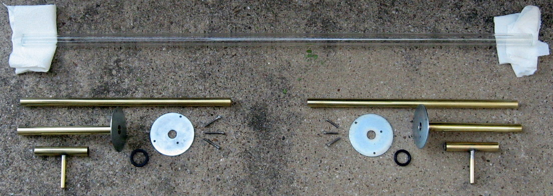
The laser tube is structurally simple. However, the actual tubing must be capable of withstanding temperatures in the 500 C range. This means that ordinary glass tubing will not work. There were plans for such a laser in the Amateur Scientist column of one of the issues of the Scientific American magazine. As far as I remember, the "Amateur Scientist" article suggested the use of quartz (fused silica) tubing. Dr. Wilson did some experiments, however, and determined that Pyrex (borosilicate) glass tubing was sufficient for the temperature range required for copper chloride. This was a step in the right direction because borosilicate is relatively abundant and cheap. I purchased mine from Sundance Art Glass. Here are the individual sections that comprise my tube, prior to assembly.

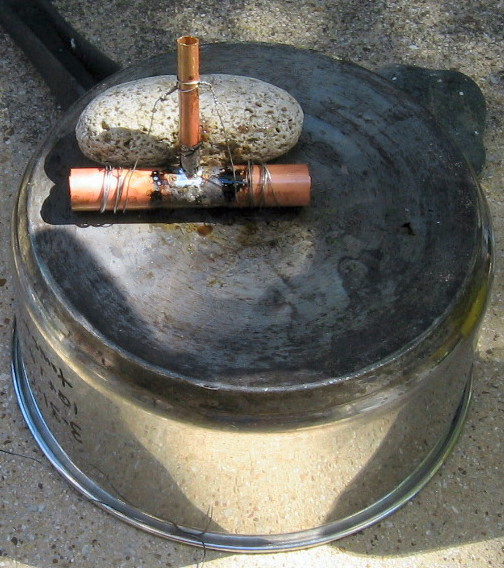
I purchased brass tubing from a local hardware store. Brass tubing was available in a range of closely gauged sizes. One size was purchased to fit inside the Pyrex tubing, and a second size was purchased to fit snugly over the first. A much smaller section was purchased as a hose connector. A short section of the smallest tubing was positioned at a right angle to the largest, and secured using tie wire. Solder was then applied at the location where the two sections joined (see below).

The piece pictured above is resting atop an old cooking pot. I used a torch to heat the sections and then applied solder. An alternative would be to use a heat gun and to place the items on a section of cement board. A heat gun will obviously not generate as much heat as a propane or map gas torch. For this reason, it is better to have the brass items on top of an insulating surface as opposed to a conductive metal surface - the metal cooking pot behaves like a heat sink. Once the solder has dried, mount the "T" shaped structure in a vise, with the smaller diameter tubing positioned vertically. Use a drill bit, perhaps 1/8 or 1/16" diameter, and drill a hole through the side of the larger tubing, from inside the smaller tubing. I recommend mounting the structure in such a way that allows access with a drill press - you will simply be drilling straight down the center of the small vertical tube, and through the side of the larger tube to which it is soldered. This smaller tube will serve as a hose connector, allowing vacuum pump access. The larger one will slide over two other sections of brass tubing, at opposite ends: one section that will be inserted into the Pyrex laser tube, and the other section onto which you will build an air-tight, adjustable mirror mount.
The inside of my pyrex tube was about 1/2 inch in diameter, and I had to locate a section of brass tubing equal in outside diameter. The brass tubing I found was a little too tight to insert into the pyrex tubing, so I had to slightly reduce the diameter. This was accomplished using an ordinary electric drill. A section of 1/4 inch metal rod was inserted into the drill and a layer of tape was built up around it. The layer of tape was applied until it became just thick enough to fit snugly inside of the brass tubing. The brass tubing was slid over this tape layer, and a layer of duct tape was then placed around the edge of the tubing. The duct tape secured the brass tubing. The tape layer, which the brass was slid over, kept the brass tubing centered around the 1/4 inch diameter rod (see below). The following photographs convey the idea, followed by the technique required to make the brass tubing fit into the Pyrex tubing.


Heater Element Mount at Rear